ATR statistics: TA4
Article from the series "ATR statistics"
TA4
The first TA for T=15 encodes the clock stop indicator (X) and the class indicator (Y). The default values are X = "clock stop not supported" and Y = "only class A supported".bits 8 and 7 indicate whether the card supports clock stop (≠ 00) or not (= 00) and, when supported, which state is preferred on the electrical circuit CLK when the clock is stopped.
- 00b: Clock stop not supported
- 01b: State L
- 10b: State H
- 11b: No preference
bits 6 to 1 indicate the classes of operating conditions accepted by the card. Each bit represents a class: bit 1 for class A, bit 2 for class B and bit 3 for class C.
- 00 0001b: A only
- 00 0010b: B only
- 00 0100b: C only
- 00 0011b: A and B
- 00 0110b: B and C
- 00 0111b: A, B and C
- Any other value: RFU
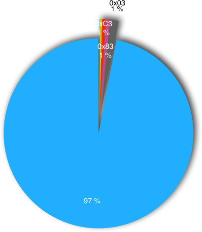
| TA4 | # | % |
|---|---|---|
| 2009 | 96.96 % | |
| 0x03 | 27 | 1.30 % |
| 0x83 | 15 | 0.72 % |
| 0xC3 | 12 | 0.58 % |
| 0x07 | 6 | 0.29 % |
| 0x43 | 2 | 0.10 % |
| 0xC7 | 1 | 0.05 % |
| Clock stop | # | % |
|---|---|---|
| not supported | 33 | 52.38 % |
| state L | 2 | 3.17 % |
| state H | 15 | 23.81 % |
| no preference | 13 | 20.63 % |
The class defines the current voltage the card can use:
- class A: 5 V
- class B: 3 V
- class C: 1.8 V
| Class | # | % |
|---|---|---|
| A & B | 56 | 88.89 % |
| A & B & C | 7 | 11.11 % |